
Technical article
How to choose and design alloy resistance
1.Rated power
Calculate power consumption operating conditions
Formula: Pavg = I2RMS × R; power (P), current (I), root mean square (RMS), resistance value (R). Allow momentary or fault conditions and high temperature environments (if applicable) to select the required power rating. For many current sensing products, the maximum temperature is only at the rated power limited by the solder joint. The rated power is only a function of the layout design of the circuit board, so the components are selected.
Determine the appropriate minimum resistance value. This is the lowest peak detection voltage value, which is in accordance with the acceptable signal-to-noise ratio, divided by the peak current for measurement.
3. Temperature coefficient (TCR)
The established accuracy requires a tolerance value for temperature sensitivity. This allowable tolerance value is often expressed as the temperature coefficient of resistance (TCR). The TCR value of low-resistance resistors is generally higher. This is because the resistance metal pins (leads) or metal interfaces cause a higher temperature coefficient, which accounts for most of the total resistance value. In order to achieve acceptable accuracy, it is usually necessary to propose a four-pin Kelvin-connected resistor.
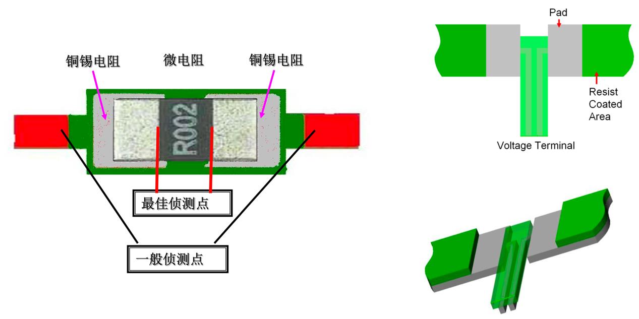
4.PCB layout
In order to realize the performance of the current detection resistor, the printed circuit board must be rigorous. The current detection should be as wide as possible, and use multi-layer vias to connect near the component. This also improves heat dissipation joints. The best method is to connect the four terminals to a two-port through-hole resistor and use the reverse side of the printed circuit board to connect the current and voltage. If this is not possible, the current and voltage sensing should be connected to the component components on both sides. In order to avoid parasitic magnetic field interference, install the detection resistor in the loop area, and the circuit input terminals for voltage and current detection should be minimized. And keep the detection circuit as close as possible to the detection resistance and voltage detection running track close to each other.
5. High frequency applications
Where instantaneous or AC currents involving high frequencies are to be detected, the self-inductance of the resistor must be minimized. Wire wound or spiral wound resistors should be avoided. Low resistance chip or metal plate resistors are the best choice.
6. High heat dissipation
When metal shunts (Shunt) are used for high heat dissipation and low detection voltages, thermoelectric voltages can be considered. The metal element and the metal port between the wiring resistors act as thermocouples, and the voltage generated is proportional to the temperature difference between the two ends. The metal-type sense resistor with pins is like two thermocouples back to back. This means that if the temperature difference across the two ports is equal, the voltage difference is cancelled out. This is through thermally symmetrical design, that is, through these two ports with similar heat sinks and keeping other distant heat sources.
7. Line layout design